This tutorial shows a really basic use case just to highlight some key aspects of the ADG canvas. For this purpose, the Lua bindings have been used for providing a more interactive (i.e. fun) experience. Nothing prevents you from using any other programming language available.
Initialization
Supposing the ADG canvas is already installed in your system, to be able to use it under Lua you must ensure you also have installed the LGI dynamic Lua bindings. This project makes any GObject introspection based library available to Lua, opening a whole set of possibilities.
Let's start coding by creating a new script with some boilerplate that pulls in the required modules.
local lgi   =     require 'lgi'
local cairo = lgi.require 'cairo'
local Cpml  = lgi.require 'Cpml'
local Adg   = lgi.require 'Adg'
local Gtk   = lgi.require 'Gtk'
Part data
We need a set of data that univocally identifies our part. For this tutorial the subject will be a bare flat washer, so we need internal diameter (d), external diameter (D) and thickness (h). We also add some metadata for identification purposes.
local data = {
    d = 6.4,
    D = 18,
    h = 3,

    -- Metadata
    code = 'M6WC',
    description = 'Flat washer',
}
Note: a simple part has been choosen to keep this tutorial as short as possible. The ADG canvas is capable of drawing much more complex parts and, in fact, it has been initially developed for drawing diesel nozzles.
Actually the data is hardcoded directly into the code. In a real world application it will probably be picked up from an external source, e.g. from a database or a web service.
Defining the models
A model is the virtual representation in 2D of the part. It is the geometrical definition of a component such as a hole, a slit or the silhouette of a view. By "virtual" it means it does not have color, thickness, filling or any other visible property.
Let's start by providing the top view of the washer, that is a couple of concentrical circles.
local function topModel()
    local path = Adg.Path {}

    local left  = Cpml.Pair { x = -data.D/2, y = 0 }
    path:set_named_pair('D0', left)

    local right = Cpml.Pair { x = data.D/2, y = 0 }
    path:set_named_pair('D180', right)

    path:move_to(left)
    path:arc_to(right, left)

    left  = Cpml.Pair { x = -data.d/2, y = 0 }
    path:set_named_pair('d0', left)

    right = Cpml.Pair { x = data.d/2, y = 0 }
    path:set_named_pair('d180', right)

    path:move_to(left)
    path:arc_to(right, left)

    path:set_named_pair('D', Cpml.Pair { x = data.D/2, y = data.D/2 })
    path:set_named_pair('d', Cpml.Pair { x = data.D/2, y = data.D/2 })

    return path
end
As you can see, there is no hardcoded values in the above code. This can or cannot be important, depending on what you want to accomplish.
A big chunk of the topModel() code is devoted to provide the so called "named pairs". These can be considered as anchors that will be used later for positioning entities and for dimension references.
Another important model is the side view, in this case a rectangle. Again, a couple of named pairs are defined for future use.
local function sideModel()
    local path = Adg.Path {}

    local pair = Cpml.Pair { x = -data.h/2, y = -data.D/2 }
    path:set_named_pair('-', pair)
    path:move_to(pair)

    pair.x = -pair.x
    path:set_named_pair('+', pair)
    path:line_to(pair)

    pair.y = -pair.y
    path:line_to(pair)

    pair.x = -pair.x
    path:line_to(pair)

    path:close()

    return path
end
For esthetical (and didactical) purposes, the side view of the section is also provided.
local function sectionModel()
    local path = Adg.Path {}

    local pair = Cpml.Pair { x = -data.h/2, y = (data.d-data.D)/4 }
    path:move_to(pair)

    pair.x = -pair.x
    path:line_to(pair)

    pair.y = -pair.y
    path:line_to(pair)

    pair.x = -pair.x
    path:line_to(pair)

    path:close()

    return path
end
Slicing a washer in the middle and viewing the cut surface from the front side gives two identical rectangles. Only one of them is defined here, just to show how a single model can be included multiple times in the drawing.
Creating the drawings
The drawing is an AdgCanvas instance that puts together one or more depictions of the model mixed with dimensions, tolerances, title block, texts, tables and whatever else required.
A single set of data can have more drawings, e.g. you can have a semifinished drafting for every manifacturing stage or an image without quotes to be shown on your web site. In this tutorial we generate only the final drawing.
local function technicalDrawing()
    local canvas = Adg.Canvas {}
    local model, view, entity, map


    -- Top view
    view = Adg.Container {
        local_map  = cairo.Matrix.create_translate(-(data.D + data.h) / 2, 0),
        global_map = cairo.Matrix.create_translate(-100, 0),
    }
    canvas:add(view)

    model = topModel()
    view:add(Adg.Stroke { trail = model })

    entity = Adg.LDim.new_full_from_model(model, 'd0', 'd180', 'd', math.pi/2)
    entity:set_value('\226\140\128 <>')
    entity:set_min('+0.1')
    entity:set_max('+0.3')
    entity:set_level(2)
    view:add(entity)

    entity = Adg.LDim.new_full_from_model(model, 'D0', 'D180', 'D', math.pi/2)
    entity:set_value('\226\140\128 <>')
    entity:set_min('-0.2')
    entity:set_max('0')
    entity:set_level(3)
    view:add(entity)


    -- Section view
    view = Adg.Container {}
    canvas:add(view)

    model = sideModel()
    view:add(Adg.Stroke { trail = model })

    entity = Adg.LDim.new_full_from_model(model, '-', '+', '+', -math.pi/2)
    entity:set_level(2)
    entity:set_min('\194\1770.05')
    view:add(entity)

    model = sectionModel()
    view:add(Adg.Stroke {
        trail = model,
        local_map = cairo.Matrix.create_translate(0, (data.d + data.D) / 4),
    })
    view:add(Adg.Hatch {
        trail = model,
        local_map = cairo.Matrix.create_translate(0, (data.d + data.D) / 4),
    })
    view:add(Adg.Stroke {
        trail = model,
        local_map = cairo.Matrix.create_translate(0, -(data.d + data.D) / 4),
    })
    view:add(Adg.Hatch {
        trail = model,
        local_map = cairo.Matrix.create_translate(0, -(data.d + data.D) / 4),
    })


    -- Canvas settings
    canvas:set_title_block(Adg.TitleBlock {
        title      = data.description,
        author     = 'ADG tutorial',
        date       = os.date('%x'),
        drawing    = data.code,
        logo       = Adg.Logo {},
        projection = Adg.Projection { scheme = Adg.ProjectionScheme.FIRST_ANGLE },
        size       = 'A4',
    })
    canvas:set_paper('iso_a4', Gtk.PageOrientation.LANDSCAPE)
    canvas:autoscale()

    return canvas
end
It is important to note that the named pairs are used either for anchoring the dimensions and for positioning them. This avoids the need to reuse explicit coordinates. Anyway, if you need to, you can still use explicit coordinates: the ADG tries hard to not force any workflow.
A big part of the logic is dedicated to dimensioning. Indeed, on complex drawings, the biggest challenge is the logic for dimension positioning. A proper drawing should be readable when feeded with every valid set of data. Sometimes also invalid or absurd sets of data need to be handled properly because you don't want to restrict the range of valid values (i.e., you don't know which new parts will be developed in the future).
Using the drawings
Once you have an AdgCanvas, you can use it for different purposes. The ADG can present the drawing in many formats so the result can be employed in many different ways. Here is a possibly non-exaustive list of use cases:
- inclusion of drawings in the product catalog;
- part of a user interface for querying a part database;
- run by the public web site to dynamically generate product images;
- embedded in the production management software.
For our tutorial let's start by providing a basic window that just shows the drawing.
local app = Gtk.Application { application_id = 'com.entidi.adg' }
function app:on_activate()
    local window = Gtk.Window {
        application = app,
        title = 'ADG tutorial',
        Adg.GtkLayout { canvas = technicalDrawing() }
    }
    window:show_all()
end
app:run { arg[0], ... }
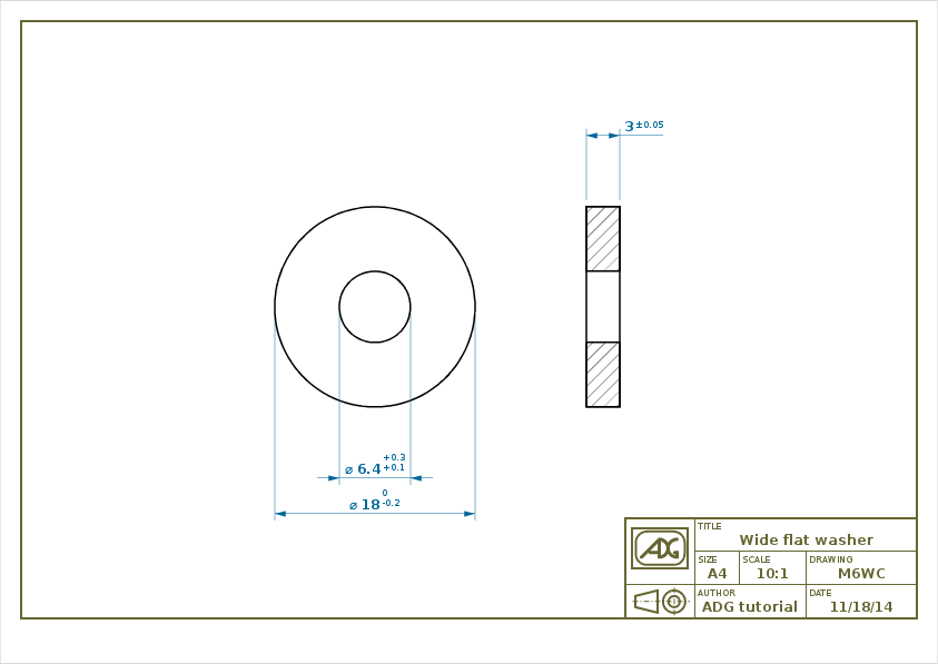
Now our application is complete! The result of the above code is shown above.
Actually, the procedure used so far seems a convoluted way of producing a technical drawing using a programming language instead of an interactive CAD. Furthermore, the arbitrary subdivision between model and view seems to just add more complexity with little gain.
But let's try to change the original data set and rerun the script to see what happens. For instance let's suppose to change the external diameter to 150, that is set D = 150. A big number has been selected in order to expose how substantial changes are handled by the ADG canvas.
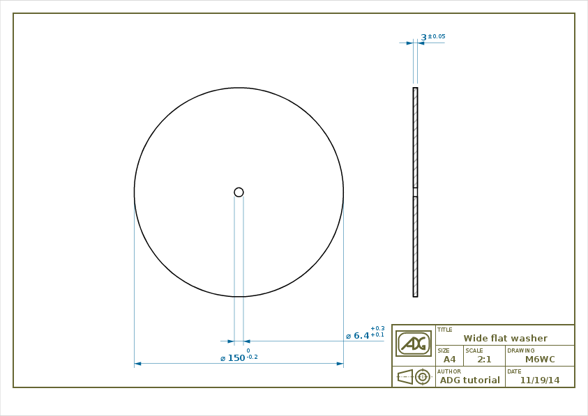
The resulting image highlights that different things have happened: and not only on the D quote side of things.
The scale has been modified to better accomodate the new model but, regardless, the size of the decorations (such as the text, the arrows, the hatches and the title block) is still the same size as before. Also, the distance of the quotes from the model is the same. Furthermore, the quote of the internal diameter has been moved outside the extension lines. This has been done because with the new scale there is not enough space to draw the quote as in the previous drawing.
And all these changes have been automatically applied by the ADG library without any additional code!
Database interface
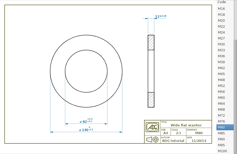
The next example shows a typical way to use the ADG canvas to browse a database of parts.
The code is the same as the one described above but the last section. To mimic a database interface, we will augment the user interface logic by including a listbox containing all the standard washers defined by the UNI 6598. Whenever the user select a washer from the list, the drawing is updated accordingly.
-- Database definition
local GObject = lgi.require 'GObject'
local db = Gtk.ListStore.new {
    GObject.Type.STRING,
    GObject.Type.DOUBLE,
    GObject.Type.DOUBLE,
    GObject.Type.DOUBLE,
}

for _, row in ipairs {
    { 'M2',        2.2,        5,        0.3 },
    { 'M3',        3.2,        7,        0.5 },
    { 'M4',        4.3,        9,        0.8 },
    { 'M5',        5.3,        10,        1 },
    { 'M6',        6.4,        12,        1.6 },
    { 'M8',        8.4,        16,        1.6 },
    { 'M10',        10.,        20,        2 },
    { 'M12',        13,        24,        2.5 },
    { 'M14',        15,        28,        2.5 },
    { 'M16',        17,        30,        3 },
    { 'M18',        19,        34,        3 },
    { 'M20',        21,        37,        3 },
    { 'M22',        23,        39,        3 },
    { 'M24',        25,        44,        4 },
    { 'M27',        28,        50,        4 },
    { 'M30',        31,        56,        4 },
    { 'M33',        34,        60,        5 },
    { 'M36',        37,        66,        5 },
    { 'M39',        40,        72,        6 },
    { 'M42',        43,        78,        7 },
    { 'M45',        46,        85,        7 },
    { 'M48',        50,        92,        8 },
    { 'M52',        54,        98,        8 },
    { 'M56',        58,        105,        9 },
    { 'M60',        62,        110,        9 },
    { 'M64',        66,        115,        9 },
    { 'M68',        70,        120,        10 },
    { 'M72',        74,        125,        10 },
    { 'M76',        78,        135,        10 },
    { 'M80',        82,        140,        12 },
    { 'M85',        88,        145,        12 },
    { 'M90',        93,        160,        12 },
    { 'M95',        99,        165,        12 },
    { 'M100',        104,        175,        14 },
} do
    db:append(row)
end

-- User interface
local app = Gtk.Application { application_id = 'org.adg.tutorial' }
local layout = Adg.GtkLayout { canvas = technicalDrawing() }
function app:on_activate()
    local tree = Gtk.TreeView {
        model = db,
        Gtk.TreeViewColumn {
            title = 'Code',
            { Gtk.CellRendererText(), { text = 1 } },
        }
    }
    local selection = tree:get_selection()
    function selection:on_changed()
        local model, iter = self:get_selected()

        -- Update the drawing
        data.code = model[iter][1]
        data.d = model[iter][2]
        data.D = model[iter][3]
        data.h = model[iter][4]
        canvas = technicalDrawing()
        layout:set_canvas(canvas)
        layout:queue_draw()
    end
    local window = Gtk.Window {
        application = app,
        title = 'ADG tutorial',
        Gtk.HBox {
            layout,
            Gtk.ScrolledWindow {
                min_content_width = 80,
                tree
            }
        }
    }
    window:show_all()
end
app:run { arg[0], ... }
This is a fully-functional application that allows you to browse the full set of UNI flat washers!
The first chunk of code is dedicated to the database definition: in a real application the database would probably resides on an external resource and db would be populated with a loop on that resource. Furthermore, the user interface could include a search feature or any other mean to make the search on a big dataset easier.
Although all valid points, this is outside the scope of this tutorial and, more in general, of the ADG project.
The material presented here only scratches the surface of the ADG. A more complex example (that did not fit a quick tutorial) is the adg-demo, a program that shows how to use the ADG to create a new part, implemented either as a desktop and as a web application. Its sources are included directly in the ADG tarball.